Daikin WMC Specifications Page 11
- Page / 64
- Table of contents
- BOOKMARKS
- Model WMC 1
- Table of Contents 3
- The New Compressor Technology 4
- Greater Reliability 5
- Exceptional Control 6
- Unit Control Features 7
- MicroTech II 8
- Changing Setpoints 9
- Trend Logging 9
- Operating Economy 9
- Give You Even More Control 10
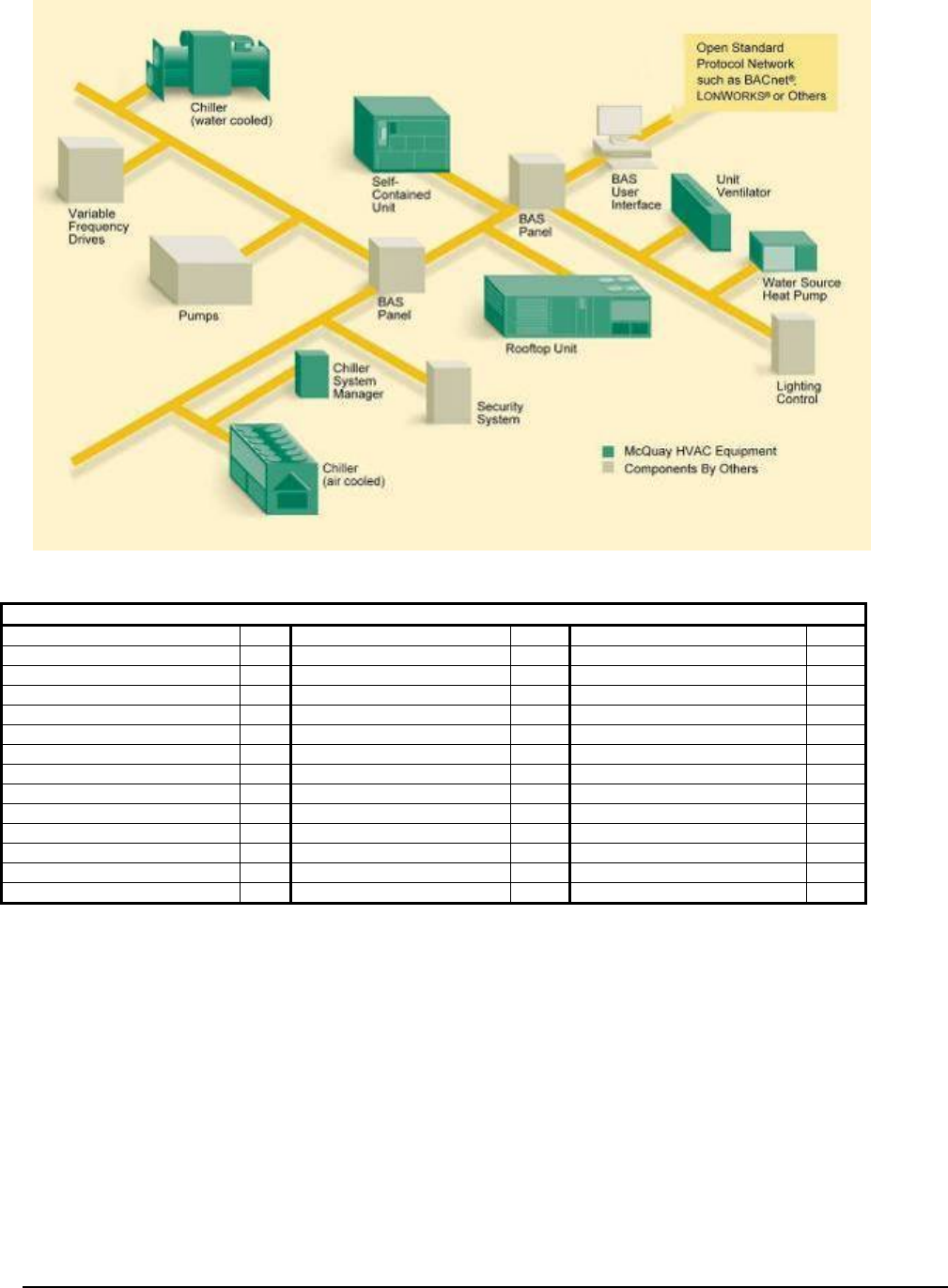
- Building Automation Systems 10
- Network Protocol Options 11
- Unit Design Features 12
- Catalog 602-2 13 13
- AHRI Certification 14
- Weighting 15
- Tolerances 15
- Chiller Identification 16
- Sound Data 17
- 18 Catalog 602-2 18
- Dimensions 19
- WMC 145DBS 20
- WMC 150DBS 21
- WMC250DBS 22
- WMC 290DBS 23
- WMC400DBS 24
- Catalog 602-2 25 25
- Drawing Notes 26
- Physical Data and Weights 27
- Physical Data 28
- Relief Valves 29
- Electrical Data 30
- Continued next page 31
- WMC 400D 3/60/460 ONLY 36
- Catalog 602-2 37 37
- 38 Catalog 602-2 38
- Power Factor Correction 39
- VFD Line Harmonics 39
- The IEEE 519-1991 Standard 40
- Application 41
- Considerations 41
- Condenser Water 42
- Temperature 42
- Variable Speed Chilled 42
- Water Pumping 42
- System Water Volume 43
- Pump Control 43
- Retrofit Knockdown 44
- Pressure Drop Curves 45
- Figure 20, 2-Pass Condensers 46
- (3 pass) 47
- Options and Accessories 48
- Electrical 49
- Refrigerant Recovery Units 50
- Refrigerant Monitors 51
- SPECIFICATIONS 52
- OPTIONS and ACCESSORIES 52
- Specifications 53
- 54 Catalog 602-2 54
- Catalog 602-2 55 55
- Octave Band 56
- Catalog 602-2 57 57
- 58 Catalog 602-2 58
- Catalog 602-2 59 59
- • Modbus 60
- • BACnet IP, (Annex J) 60
- Catalog 602-2 61 61
- Catalog 602-2 (2/12) 64
Related products and manuals for Heat pumps Daikin WMC
 (16 pages)
(48 pages)
(40 pages)
(16 pages)
(48 pages)
(40 pages)
 (36 pages)
© 2020, manymanuals.com. All rights reserved. | 0.059 s |
 Manymanuals.com
 Manymanuals.de
 Manymanuals.fr
 Manymanuals.it
 Manymanuals.pl
 Manymanuals.cz
 Manymanuals.es
 Manymanuals-pt.com
Comments to this Manuals