Daikin BRC1E72 Installation Manual Page 1
Browse online or download Installation Manual for Remote controls Daikin BRC1E72. Daikin BRC1E72 Installation manual [en] [es] User Manual
- Page / 72
- Table of contents
- BOOKMARKS
- WIRED REMOTE 1
- CONTROLLER 1
- Contents 3
- Safety Considerations1 4
- CAUTION 5
- Accessories2 6
- Install wiring.3-5 7
- Back outlet3-5-1 8
- Left outlet3-5-2 9
- Top left outlet3-5-3 9
- Top center outlet3-5-4 9
- Wall installatoin3-6-1 10
- Switch box installation3-6-2 10
- Install the upper case. 3-7 11
- Functions and menu items4-1 12
- English 11 13
- Power-on5 14
- Field Settings6 15
- 14 English 16
- Test Operation7 17
- 16 English 18
- English 17 19
- 18 English 20
- Information 21
- Clock & Calendar11 22
- Language12 23
- 22 English 24
- Table des matières 25
- Considérations de sécurité1 26
- ATTENTION 27
- REMARQUE 27
- Accessoires2 28
- Installez le câblage.3-5 29
- REMARQUE 29
- Sortie arrière3-5-1 30
- Sortie gauche3-5-2 31
- 10 Français 34
- Marche5 36
- Réglages locaux6 37
- Opération test7 39
- 16 Français 40
- 18 Français 42
- Français 19 43
- 20 Français 44
- Heure & calendrier11 45
- Langue12 46
- Contenidos 47
- ADVERTENCIA 48
- PRECAUCIÓN 49
- Accesorios2 50
- Instale el cableado.3-5 51
- Salida posterior3-5-1 52
- Salida izquierda3-5-2 53
- Salida central superior3-5-4 53
- Instalación en la pared3-6-1 54
- Español 9 55
- Botones del Control Remoto 56
- Español 11 57
- Encendido5 58
- Ajustes de Campo6 59
- 14 Español 60
- Prueba de Operación7 61
- 16 Español 62
- Español 17 63
- 18 Español 64
- Español 19 65
- 20 Español 66
- Registrados 67
- Reloj y Calendario11 67
- Lenguaje12 68
- 3P243521-3D 72
Summary of Contents
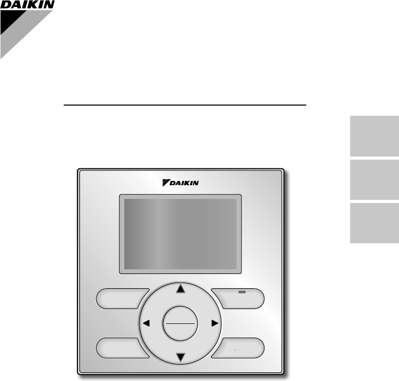
EnglishFrançaisEspañolBe sure to read this installation manual before installing this product.On/OffModeFanSpeedCancelMenuOKMODEL BRC1E72WIRED REMOTE
8 English ● To prevent electrical noise and possible communication errors, avoid installing the remote controller cabling parallel to or in the vicin
English 9Switch box(field supply)(Use optional accessory KJB111A)Small screws (M4×16mm)Switch box for one unit (with no cover) 3-5/161-1/8(Installati
On/OffModeFanSpeedCancelMenuOK10 EnglishFunctions and menu items of remote 4. controller buttonsFunctions and menu items4-1 Operation mode selector b
English 11Left button (7) Used to highlight items to the left of the ●currently selected item.Display contents are changed to ●previous screen per
12 EnglishPower-on5. Check for completion of indoor/outdoor unit wiring. ●Ensure that covers have been replaced on electrical component boxes for bo
English 13Field Settings6. 6-1 Press and hold Cancel button for 4 seconds or longer. Service settings menu is displayed.Select 6-2 Field Settings
14 English6-6 Press Menu/OK button. Setting confi rmation screen is displayed.Select 6-7 Yes and press Menu/OK button. Setting details are determi
English 15Notes) Field settings are normally applied to the entire remote control group, however if individual 1. indoor units in the remote control
16 English7-4 Press On/Off button within 10 sec-onds, and the test operation starts. Monitor the operation of the indoor unit for a minimum of 10 min
English 17 ●If operation is not possible due to a malfunction, refer to following Failure diagnosis method .After the test operation fi nishes, check
18 EnglishRemote controller display DescriptionNo displayPower outage, power voltage error or open-phase ●Incorrect wiring (between indoor and outdo
English 19Entering Maintenance Contact 9. InformationRegistration of the maintenance contact. ●9-1 Press and hold Cancel button for 4 seconds or long
20 EnglishConfi rmation registered details10. 10-1 Press Menu/OK button in the basic screen. Main menu is displayed.Select Maintenance Information i
English 2111-3 Select year, month, day and time by using (Left/Right) button and set by using (Up/Down) button in the Date & Time screen. P
22 English01_EN_3P243521-3D.indd 2201_EN_3P243521-3D.indd 22 9/13/2012 7:22:23 PM9/13/2012 7:22:23 PM
Français 1Table des matières1. Considérations de sécurité ... 22. Accessoires ... 43. Procédure
2 FrançaisConsidérations de sécurité1. Toutes les phases de l’installation locale, y compris, mais non limité à, l’installation du système électrique
Français 3 ATTENTIONÉvitez toute pénétration d’eau dans la télécommande. Pour éviter tout choc électrique provoqué par une pénétration d’eau ou d’in
4 FrançaisAccessoires2. Les accessoires suivants sont inclus.Vis à bois Petite vis BrideManuel d’utilisationManuel d’installationRetenue de câblage(φ
Français 5Déterminez l’emplacement auquel le câblage pénètrera 3-4 dans la télécommande (côtés arrière, gauche, supérieur gauche, supérieur central).
English 1Contents1. Safety Considerations ... 22. Accessories ... 43. Remote controller in
6 FrançaisPréparez le câblage pour la connexion à la télécommande en procédant comme suit:Retirez la gaine du câble et l’isolantLignes guides de coup
Français 7Sortie gauche3-5-2 Boîtier inférieurBoîtier supérieurUnité intérP1P2Plaquette de circuits imprimésSortie supérieure gauche3-5-3 Comme indiq
8 Français ● Pour éviter tout bruit électrique et toute erreur de communication, évitez d’installer le câblage de télécommande parallèlement ou au vo
Français 9Boîtier électrique(fourni sur place)(Utilisez l’accessoire en option KJB111A)Petites vis (M4×16mm)Boîtier électrique pour une unité (sans c
On/OffModeFanSpeedCancelMenuOK10 FrançaisFonctions et articles du menu des 4. boutons de la télécommandeFonctions et articles du menu4-1 Bouton de sé
Français 11Bouton Bas (5) Ce bouton est utilisé pour abaisser le ●point de réglage de la température.Les articles situés au-dessous de l’article ●a
12 FrançaisMarche5. Vérifi ez que le câblage des unités intérieure/extérieure est terminé. ●Vérifi ez que les couvercles ont bien été remis en place s
Français 13Réglages locaux6. 6-1 Appuyez sur le bouton Annuler et maintenez-le enfoncé pendant au moins 4 secondes.Le menu des réglages service s’affi
14 Français6-6 Appuyez sur le bouton Menu/OK. L’écran de confi rmation de réglage s’affi che.Sélectionnez 6-7 Oui et appuyez sur le bouton Menu/OK. L
Français 15Mode No.(Remarque 1)PREMIER NO. DE CODEDescriptionSECOND NO. DE CODE (Remarque 2) (Les articles en caractères gras sont les réglages par
2 EnglishSafety Considerations1. All phases of the fi eld-installation, including, but not limited to, electrical, piping, safety, etc. must be in acc
16 Français7-1 Réglez le mode de fonctionnement sur rafraîchissement en utilisant la télécommande.Appuyez sur le bouton 7-2 Annuler et maintenez-le
Français 177-9 Sélectionnez Opération test dans le menu des réglages service et appuyez sur le bouton Menu/OK. L’écran de base retourne et le fonct
18 Français7-12 Appuyez sur le bouton Menu/OK sur l’écran de base. Le menu principal s’affi che.Sélectionnez 7-13 Contact / modèle dans le menu pri
Français 19Affi chage de la télécommande DescriptionPas d’affi chageCoupure de courant, erreur de tension d’alimentation ou ●phase ouverteCâblage inco
20 FrançaisEntrée des informations Contact 9. dépannageEnregistrement du contact dépannage. ●9-1 Appuyez sur le bouton Annuler et maintenez-le enfonc
Français 21Confi rmation des détails enregistrés10. 10-1 Appuyez sur le bouton Menu/OK sur l’écran de base.Le menu principal s’affi che.Sélectionnez C
22 Français11-3 Sélectionnez année, mois, jour et heure en utilisant le bouton (Gauche/Droite) et effectuez le réglage en utilisant le bouton (
Español 1Contenidos1. Consideraciones de Seguridad ... 22. Accesorios ... 43. Procedimiento de Instal
2 EspañolConsideraciones de Seguridad1. Todas las fases de la instalación de campo, incluyendo pero no limitado a la electricidad, tuberías, segurida
Español 3 PRECAUCIÓNMantenga el agua fuera del control remoto.Para evitar descargas eléctricas debido a la entrada de agua o insectos, llene el orifi
English 3 CAUTIONKeep water out of the remote controller. To avoid electric shock due to entry of water or insects, fi ll the wiring through-hole wit
4 EspañolAccesorios2. Se incluyen los siguientes accesorios.Tornillo de maderaTornillo pequeñoAbrazaderaManual de operaciónManual de instalaciónReten
Español 5Determine la localización donde el cableado entrará al 3-4 control remoto (lado posterior, izquierdo, parte izquierda superior, parte centra
6 EspañolPrepare el cableado para conexión al control remoto siguiendo estas instrucciones:Extraiga el forro del cable y el aislamientoInstructivo de
Español 7Salida izquierda3-5-2 Caja inferiorCaja superiorUnidad interioP1P2Tablero de circuitos impresosSalida izquierda superior3-5-3 Como se muestr
8 Español ● Para evitar el ruido eléctrico y los posibles errores de comunicación, evite instalar el cable de control remoto en paralelo con, o en la
Español 9Tornillos pequeños (M4×16mm)Caja de conmutación para una unidad (sin cubierta)3-5/161-1/8(Paso de instalación)Caja de conmutación(suministro
On/OffModeFanSpeedCancelMenuOK10 EspañolFunciones e Ítemes de Menú de los 4. Botones del Control RemotoFunciones e ítemes de menú4-1 Botón selector d
Español 11Botón abajo (5) Se usa para bajar la temperatura del ●punto de ajuste.Los ítemes bajo el ítem actualmente ●seleccionado serán destacados.
12 EspañolEncendido5. Verifi que que se ha completado el cableado de la unidad interior/exterior. ●Asegúrese que las cubiertas hayan sido repuestas e
Español 13Ajustes de Campo6. 6-1 Presione y mantenga presio-nando el botón Cancelación por 4 segundos o más.Se visualiza el menú de ajustes de servic
4 EnglishAccessories2. The following accessories are included.Wood screw Small screw ClampOperation manualInstallation manualWiring retainer(φ3.5×16m
14 Español6-6 Presione el botón de Menú/OK. Se visualiza la pantalla de confi rmación de ajuste.Seleccione 6-7 Si y presione el botón de Menú/OK. S
Español 15Nº de modo(Nota 1)PRIMER Nº DE CÓDIGODescripciónSEGUNDO Nº DE CÓDIGO (Nota 2)(Los ítemes en negrilla son los ajustes por defecto de fábric
16 Español7-1 Ajuste el modo de operación a enfriamiento usando el control remoto.Presione y mantenga presionando el 7-2 botón Cancelación por 4 segu
Español 177-9 Seleccionet Prueba de Operación en el menú de ajustes de servicio, y presione el botón de Menú/OK. La pantalla básica retorna y se ef
18 Español7-12 Presione el botón de Menú/OK en la pantalla básica. Se visualiza la pantalla del menú principal.Seleccione 7-13 Info de Mantenimien
Español 19Visualización del control remoto DescripciónNo hay visualizaciónCorte de alimentación, error de voltaje eléctrico o fase ●abiertaCableado
20 EspañolIngreso de la Información de Contacto 9. de MantenimientoRegistro del contacto de mantenimiento. ●9-1 Presione y mantenga presionando el bo
Español 21Confi rmación de los Detalles 10. Registrados10-1 Presione el botón de Menú/OK en la pantalla básica.Se visualiza el menú principal.Seleccio
22 Español11-3 Seleccione año, mes, día y hora usando el botón (Izquierda/Derecha) y ajústelo usando el botón (Arriba/Abajo) en la pantalla de f
English 5Determine the location where the cabling will enter the 3-4 remote controller (back, left side, top left, top center).Back outlet3-4-1 Left
3P243521-3D EM12A024 (1209) HT 00_CV_3P243521-3D.indd 400_CV_3P243521-3D.indd 4 9/11/2012 3:09:14 PM9/11/2012 3:09:14 PM
6 EnglishPrepare the cabling for connection to the remote controller following these instructions:Remove the cable jacket and insulationCutting guide
English 7Left outlet3-5-2 PC-boardLower caseUpper caseIndoor unitP1P2Top left outlet3-5-3 As shown to the left, install the attached retainer to prev
More documents for Remote controls Daikin BRC1E72


Related products and manuals for Remote controls Daikin BRC1E72
 (32 pages)
(22 pages)
(58 pages)
(32 pages)
(22 pages)
(58 pages)
 (33 pages)
(12 pages)
(33 pages)
(12 pages)
 (8 pages) (26 pages)
(28 pages)
(20 pages)
(22 pages)
(139 pages)
(8 pages) (26 pages)
(28 pages)
(20 pages)
(22 pages)
(139 pages)
© 2020, manymanuals.com. All rights reserved. | 0.038 s |
 Manymanuals.com
 Manymanuals.de
 Manymanuals.fr
 Manymanuals.it
 Manymanuals.pl
 Manymanuals.cz
 Manymanuals.es
 Manymanuals-pt.com
Comments to this Manuals